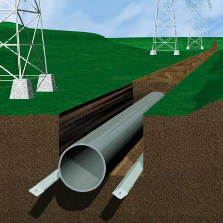
In these systems, A.C. voltages are transmitted to the pipeline by conductive or inductive interference. Magnetic induction acts along the pipeline or pipeline segment that is approximately parallel to the power line and can cause significant pipeline potentials even at relatively large separation distances.
Consideration must be given to safety of personnel and the public who may come into contact with above ground portions of the pipeline such as valves and test stations. These exposed structures can be a potential shock hazard when touched while the soil is at a significantly different potential.
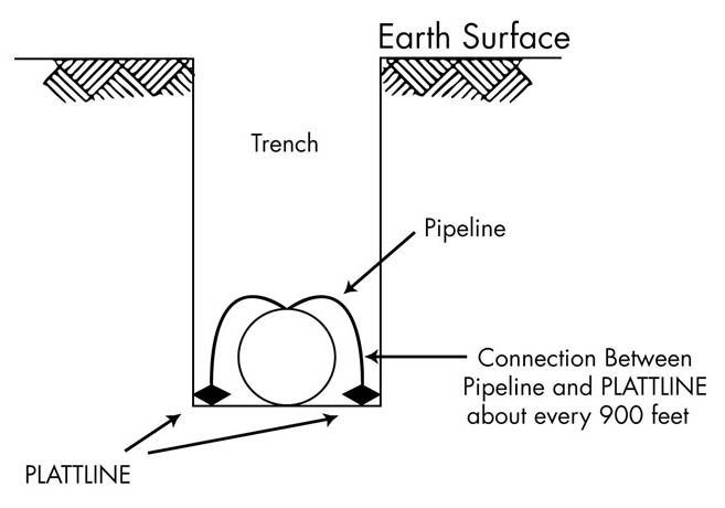
Advances in interference control have resulted in the gradient control wire method. This method consists of one or more bare zinc conductors buried parallel to and near the pipeline and regularly connected to it. Plattline™ zinc ribbon anode used in this way is very effective in mitigating excessive pipeline potentials due to both inductive and conductive interference.
It is important to review the use and design of a gradient control wire system with an engineer experienced with this system, as its performance will depend on the multi-layered structure of the earth.
For inductive interference, gradient control wires provide additional grounding for the pipeline and decrease the induced pipe potential rise. At the same time, they raise local ground potentials, thus sharply reducing touch potentials and coating stress voltages.
For conductive interference, gradient control wires dampen the soil potential rise close to the pipe while raising pipe potentials, providing reduced touch voltages and decreasing coating stress voltages.
Life expectancy of Plattline™ in this application would be quite long and would generally be determined by Plattline™ as a projected cathodic protection system. The most common sizes of Plattline™ for AC mitigation are plus and standard.
Plattline™ can provide a significant means to mitigate potential gradients along the length of a pipeline. Importance must also be placed on reducing the potentials at valve sites, metering stations, pig launchers, receivers and other accessible installations for worker safety
Gradient control grids or grounding mats raise local ground potentials in the same way gradient control wires do. These grounding mats can be made in several forms. Spiral and rectangular designs are generally standard for grounding mats. These are shown in Figures 3, 4 and 5. The most common size of Plattline™ for grounding mats is standard.
Reference should be made to NACE Standard RP0177 (Latest Revision) – Recommended Practice on Mitigation of Alternating Current & Lightning Effects on Metallic Structure and Corrosion Control Systems. Also, ANSI/IEEE Standard 80 specifies safety design criteria for determining maximum acceptable touch and step voltages during fault conditions.
Finally, during fault conditions on the power line, the system must ensure that pipeline coating stress voltages remain within acceptable limits to prevent coating damage and damage to the pipeline steel. Coating damage can occur in the range of 1000 – 2000 volts for bitumen based coatings and in the range of 3000 – 5000 volts for polyethylene or fusion-bonded epoxy coated pipelines
Plattline I is an alloyed zinc product and is generally used in seawater or brackish water systems. It meets the chemical requirement of MIL-A-18001K and ASTM B418-16a Type I.
Plattline II is a high purity product and generally used in underground and fresh water systems. It meets the chemical requirements of ASTM B418-16a Type II.